![]() ISSN 0798 1015
ISSN 0798 1015

![]() ISSN 0798 1015
ISSN 0798 1015
Vol. 38 (Nº 34) Año 2017. Pág. 8
HERNANDEZ, Herrera Hernan 1; CASTELLANOS Luis M. 2; CABELLO Eras Juan J. 3; SILVA Ortega Jorge I. 4; MANGA Carlos A. 5
Recibido: 14/02/2017 • Aprobado: 02/03/2017
ABSTRACT: A failure in the bottom sheet of a bucket conveyor (KZB-Q.AUMUND) during service was investigated. Sheets are coupled to the chain throught a screw connection; they operate in variable load scenarios causing fatigue. A chemical and microstructural analysis was made showing that sheet was built in steel with 0.15 % of Carbone without alloying elements that contribute to the refined grain and resistance increase. Strength calculation, used to determinate safety factor, consider load system and type material. Results concluded that geometry and thickness value do not provide an adequate fatigue resistance coefficient. |
RESUMEN: Es investigada la falla en las láminas del fondo de un transportador de cangilones KZB-Q.AUMUND durante su servicio. Las láminas están acopladas a una cadena a través de uniones atornilladas y operan bajo un régimen de cargas variables causándoles fatiga. Se realiza un análisis químico y microestructural el cual evidencia que las láminas fueron elaboradas de un acero con 0,15 % de carbono sin elementos de aleación que contribuyan al afinamiento del grano y al incremento de la resistencia. Se calculan las tensiones para determinar el coeficiente de seguridad a la fatiga considerando el sistema de cargas y el material de las láminas. Los resultados concluyen que la geometría y los valores de espesor no le proporcionan a las láminas un adecuado coeficiente de resistencia a la fatiga. |

In cement industry, a high number of raw material and products are processed and transported during manufacturing process; those involved equipment have significance in company’s productivity. Conveyors used to drive raw materials in cement industry usually are bands and bucket conveyors. The last ones are used commonly in Clinker transportation and finished final products which are driven to storage rooms. These systems are selected according with material properties, load requirements and lifting [1], [2].
Mechanical failures are usually attributed to non-compliance maintenance intervals, errors during design such as material selection, assemblies or incorrect operation [3], [4]. These failures conditions are in disagree with industry expectances which specify that critical equipment must be defect-free and systematic failure that cause stops in processes, increasing operation cost and delays during deliveries, affecting finances due to markets requirements and competitiveness [5 ]-[7].
This paper analyze a case study to determinate failure causes in the bottom sheet of the bucket conveyor KZB-Q Clinker Conveyor-AUMUND in Colombian Cement Company. The reviewed unit evidenced four failures between July and December 2015, producing considerable financial losses.
In order to identify failure causes a chemical and microstructural analysis at material using for bottom sheet manufacturing was carried out, also mechanical properties of the material were studied and resistance to fatigue assessment was developed [8-12].
Fig. 1 shows location and magnitude failure in the analyzed bucket conveyor. The chemical analysis to the specimens of the bottom sheet was performed using an optical emission spectrometer OLYMPUS GX41. Nital solution of 2% was used as attack element.
ASTM E-3 [13], E-407 [14] and E-45 [15] were used for preparation, chemical attack and non-metallic inclusions calculus respectively. A tensile test was realized in specimens using ASTM A-370 [16] using a 60 tons Shimadzu universal Machine. The media Brinell hardness was obtained in a Wilson Hardness Tester using ASTM 92-82 [17].
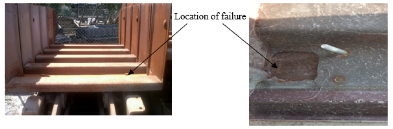
Fig. 1 . Failure location and magnitude.
The fatigue resistance coefficient calculus begin using a free body diagram representation in order to obtain loads that appear on the bottom sheets conveyor. Sheets were drawn using Mechanical Desktop 6.0 and with calculated loads, it is modeled using finite elements method with the software Cosmos Design Star 4.0. With the stress values and load cycle effort it is calculated the sheet fatigue resistance coefficient.
Results, showed in table 1, evidenced that steel used is carbon steel without alloy elements and micro-alloy refined grain. The low carbon level guarantee an adequate weldabillity but this reduce hardness property, mechanical resistance and fatigue resistance.
Table 1. Chemical analysis on the bucket sheet conveyor
Element |
wt.% |
Element |
wt.% |
Carbon |
0,149 |
Molybdenum |
0,014M |
Silicon |
0,213 |
Nickel |
0,086 |
Manganese |
0,599 |
Copper |
0,292 |
Phosphorus |
0,14 |
Aluminum |
0,0067 |
Sulfur |
0,041 |
Titanium |
0,0015 |
Chrome |
0,086 |
Niobium |
0,018 |
Specimens without attack showed nonmetallic shapes derived from Type A oxides. Using chemical attack, it was detected high ferrite levels and very low pearlite presence as is shown in a micrographic analysis presented in Fig. 2 .
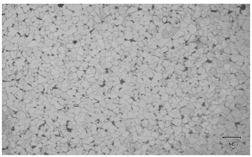
Fig. 2 . Optical micrograph analysis
The steel average hardness was 135 HB, otherwise the average mechanical resistance measured were 223 MPa in the yield strength and 345 MPa with the maximum tensile value, they correspond to the structure type and low carbon steel percentage.
The conveyor operates with a transmission chain joined to the bottom sheet using screw connections. Two wheels located at both ends support this; connections between wheels and conveyor is realized through wheels axis, which is fixed to a “U” profile, welded in the bottom sheet. The distance between the farthest Union “U” point and the wheel support is 177 mm as is shown in Fig. 3 .
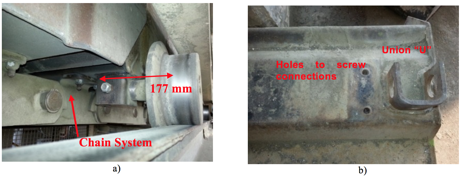
Fig. 3 . Joint elements of the bottom sheet with chain drive and supports.
Forces values on the conveyor were calculated using information provided by industry. Conveyor moving parts weight has a value of 4.84 kN/m including chain transmission. The maximum Clinker weight value deposited in the conveyor is 3.1 kN/m. As is shown in Fig. 4 , the distance value is 1.5 m; the maximum weight value is presented in Fig. 5 and determined as follow:
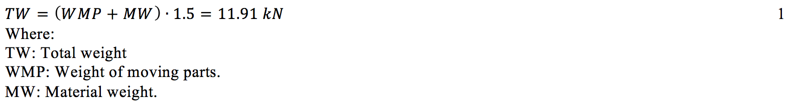
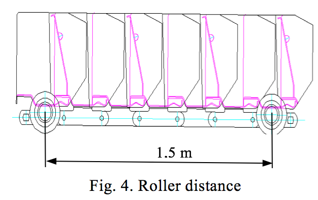
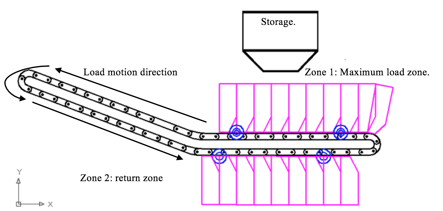
Fig. 5 . Bucket conveyor KZB-Q Pan conveyor – Aumund geometry.
Considering the total weight (TW) and taking into account that the system is symmetric, on each wheel is registered a force reaction of 5.59 kN. Reactions in the return (zone 2) only consider the weight from moving parts obtaining a reaction of 2,42 kN.
In order to realize fatigue analysis, there were calculated tensile values in both zones:
The maximum force value in the sheet is applied in the farthest point from the “U” weld point. The force is transmitted from structures supports using the axis lane as is shown in Fig. 3 a). The sheet was modeled using the software Mechanical Desktop 6.0 for the design and the software Cosmos Design Star 4.0 for simulations. During modeling, there was considered a parabolic tetrahedral mesh, it allowed better results in order to have an adequate contour representation [18- 21]. In all models was realized a progressively convergence refining study until obtain a difference between stress value for the definitive model and the previous model with a value lower than 5%, ensuring that local maximum stress values do not depend from the used mesh size [22], [23]. Using finite element method it was obtained for the forces in zone 1 a stress value equal to 89,7 MPa and 32,42 MPa for Zone 2. These results are shown in Fig. 6(a-b).
As it is observed in Fig. 6 , the sections where was located the maximum stress value correspond to the failure section as is shown in Fig. 7 .
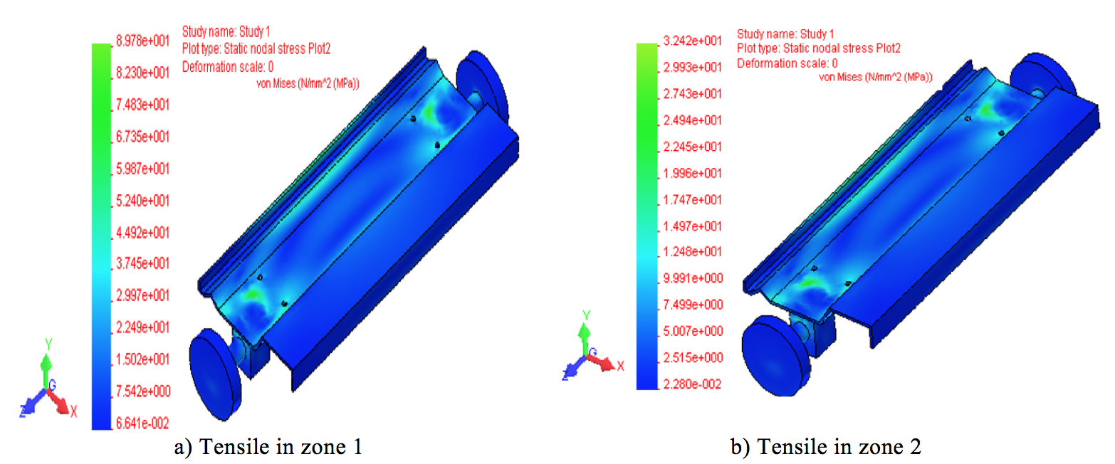
Fig. 6 . Support the axle of the wheel in the bottom sheet conveyor and Tensile in zone 1 and 2
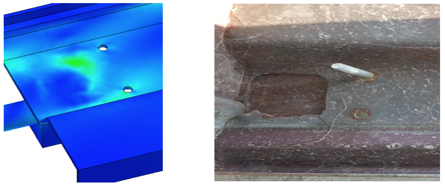
Fig. 7 . Point where the stress value of the sheet is maximum and place of the failure.
Fig. 5 evidenced that the conveyor bottom sheet has worked using variable stress values during operation. For this cycle there were determined the asymmetry, the average tensile during the cycle and the amplitude tensile value [8].
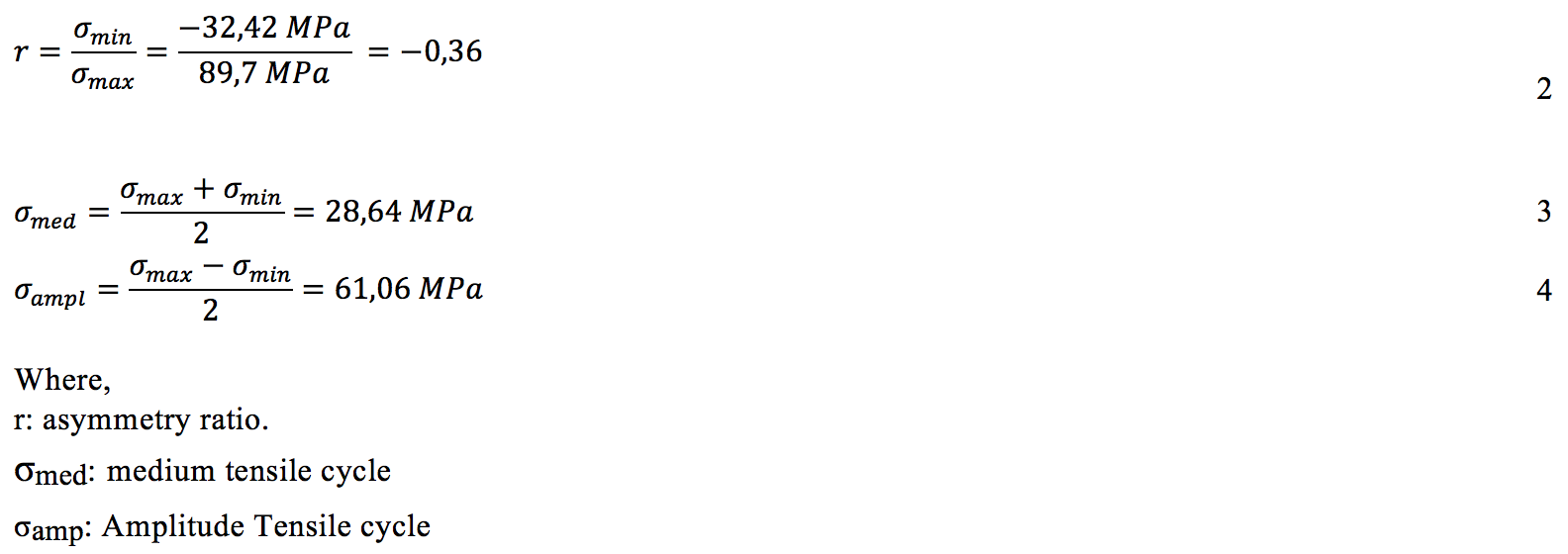
The fatigue safety factor for a cycle must be -1≤r≤0 according with [8], as follow:
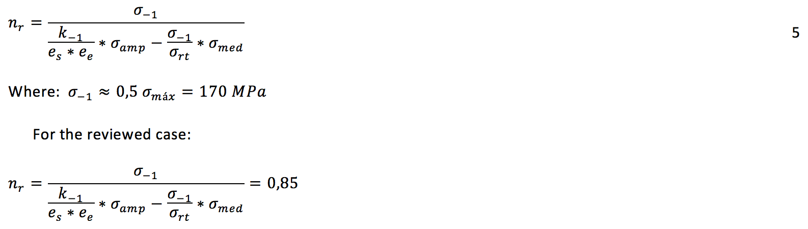
The coefficients of the equation were taken from [24], [25] and their values are presented in Table 2 :
Table 2 . Coefficients used for Fatigue Safety Factor.
Abbreviation |
Description |
Value |
K-1 |
Tensile concentration factor |
1,70 |
es |
surface quality coefficient |
0,68 |
ee |
Scale factor coefficient |
0,72 |
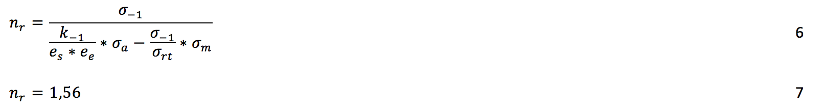
The Fatigue Safety Factor is very low, for that reason the bottom sheet conveyor will fail after a number of operation cycles as has occurred previously during the process. A bottom sheet with better properties such as ASTM A 715 80° could be a feasible solution [26]. This steel has low carbon content (0.15), it provides good weldability and better mechanical properties because its yield strength is 520 MPa (higher than the used) and its maximum tensile value is 620 MPa (higher that the used). These values increase the Fatigue Safety Factor as follow:
Bucket conveyor was made with a standard steel with low carbon content, which implies a low mechanical resistance and good weldability. The resistance analysis showed that bottom sheet geometry and thickness does not provide an adequate fatigue safety factor, for that reason after a number of cycles it will fail for this reason.
In order to increase the fatigue safety factor there are solutions such as increase the bottom sheet thickness or replace the sheet with a more resistance material such as the ASTM A 715 80 degrees, it provides an adequate fatigue safety factor.
1. Grupo de Investigación en Optimización Energética GIOPEN. Universidad de la Costa, CUC. email hhernand16@cuc.edu.co
2. Grupo de Investigación GEMAS. Facultad de Ingeniería. Universidad Simón Bolívar, email luis.catellanos@unisimonbolivar.edu.co
3. Grupo de Investigación en Optimización Energética GIOPEN. Universidad de la Costa, CUC. Email jcabello2@cuc.edu.co
4. Grupo de Investigación en Optimización Energética GIOPEN. Universidad de la Costa, CUC. email jsilva6@cuc.edu.co
5. Grupo de Investigación GEMAS. Facultad de Ingeniería. Universidad Simón Bolívar, email c.andres.manga@gmail.com