![]() ISSN 0798 1015
ISSN 0798 1015

![]() ISSN 0798 1015
ISSN 0798 1015
Vol. 38 (Nº 44) Año 2017. Pág. 9
Alex Cristiano RODRIGUES 1; Estaner Claro ROMÃO 2; Luiz Felipe Mendes de MOURA 3; Jairo Aparecido MARTINS 4
Recibido: 08/05/2017 • Aprobado: 11/06/2017
ABSTRACT: This work presents the utilization of a numerical model to determine the hydrodynamic forces acting on flat wagon floodgates, utilized in the diversion works of Hydroelectric Plants. For this purpose, the commercial software FluentTM was applied satisfactorily. Three-dimensional numerical models for various openings of the radial stop log gate were generated, which is ultimately responsible for closing the diversion. The validation of the numerical model was done by comparing data from a reduced physical model, previously studied in laboratory - where it was found the correct capture and interpretation of the hydraulic phenomena present – and the numerical model (methodology) applied in similar / derivative works. |
RESUMO: Este trabalho apresenta a utilização de um modelo numérico para determinar as forças hidrodinâmicas atuando em comportas de carroças planas, utilizadas nas obras de diversão das usinas hidrelétricas. Para este efeito, o software comercial FluentTM foi aplicado satisfatoriamente. Os modelos numéricos tridimensionais para várias aberturas da porta de registro de parada radial foram gerados, o que é finalmente responsável por fechar a diversão. A validação do modelo numérico foi feita através da comparação de dados de um modelo físico reduzido, previamente estudado em laboratório-onde foi encontrado a captura correta e interpretação dos fenômenos hidráulicos presentes-e do modelo numérico (metodologia) aplicado em trabalhos similares/derivados. |

Many are the efforts applied in hydraulic engineering in order to provide to the discipline of fluid dynamics more and more complex solutions under higher reliability. In this sense, it compiles and consider a large number of data and variables, resulting in complex systems of equations (Tao Wang, 2013), (SUN Bin, 2013). The utilization of computational resources for this purpose, search for - through mathematical models - a set of methods and techniques for better interpretation and understanding of the physics implied in many different problems (Sarasúa, 2014). In real applications, where the geometrical characteristics of the problems are complex, the computer simulation has proved as being a powerful tool to assist scientists and engineers (Kuiyi Zhou, 2014).
In practical basis, the analysis and measurements utilizing reduced physical models are, by far, the most reliable results to determine the hydrodynamic forces present in radial gates. From the numerical validation standpoint, the proposal of this paper is to solve problems related to hydraulic engineering, aiming to verify the ability of this numerical method to reproduce the same hydrodynamic effects, previously obtained in laboratory.
The generation of this numerical model targets on determining the hydrodynamic forces acting on radial gates on diversion tunnels of hydroelectric plants. In order to have the most accurate numerical model, previously the well-known method of “Theory of Similarity” (Motta, 1972) was used to build the reduced physical model. By the comparison of both results, reduced physical model versus numerical model, the reliability of the last is guaranteed. With the numerical model validated, it may be applied for similar and/or derivative studies. In the context, of shorten engineering time, accurate numerical models in replacement to the reduced physical ones has become a reality - once it consumes reduced workforce and costs – and mainly keeping the same quality of results when compared with the physical model.
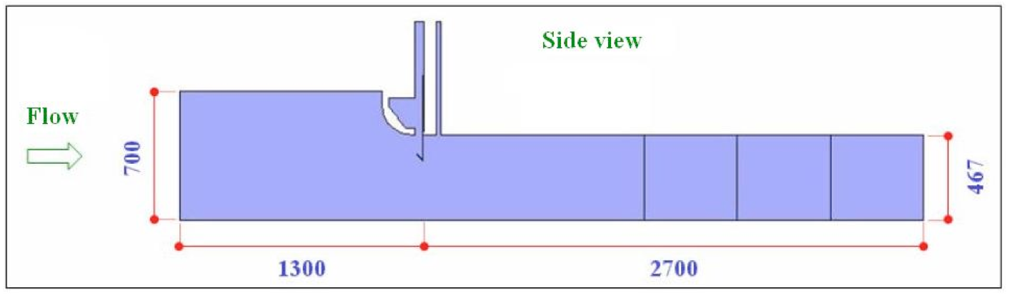
Fig. 1 Side view of the three dimensional numerical model.
The validation of the proposed numerical model was performed with the same geometrical parameters utilized in the reduced physical model made from Machadinho Hydroelectric Power Plant [HPP] (Rodrigues, 2010), where the geometry was generated on 1:30 scale (CTH, 1998). The numerical model regarding the main dimensions, in millimeters, is shown in Figures 1-3.
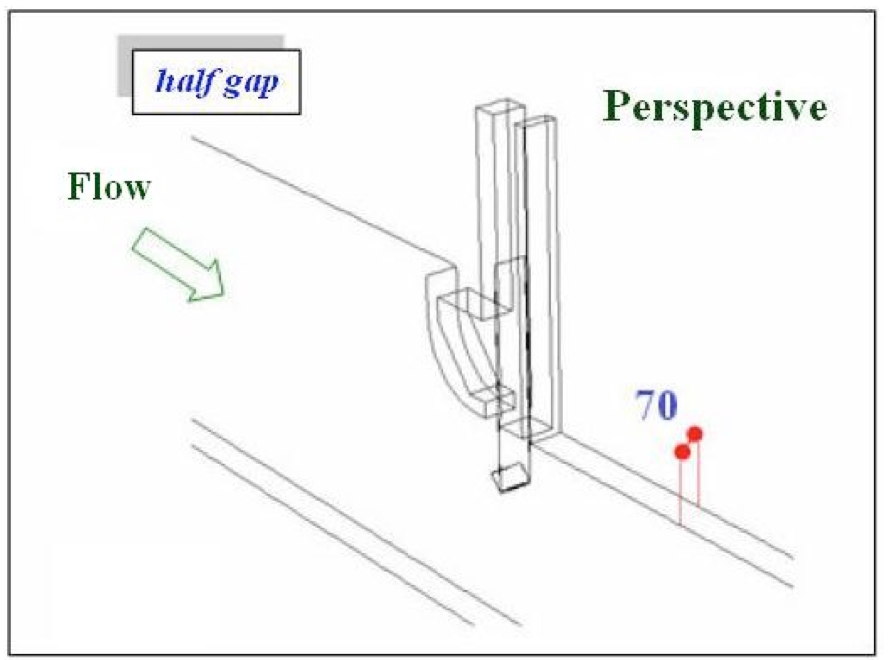
Fig. 2 Perspective of part of the three dimensional numerical model.
----
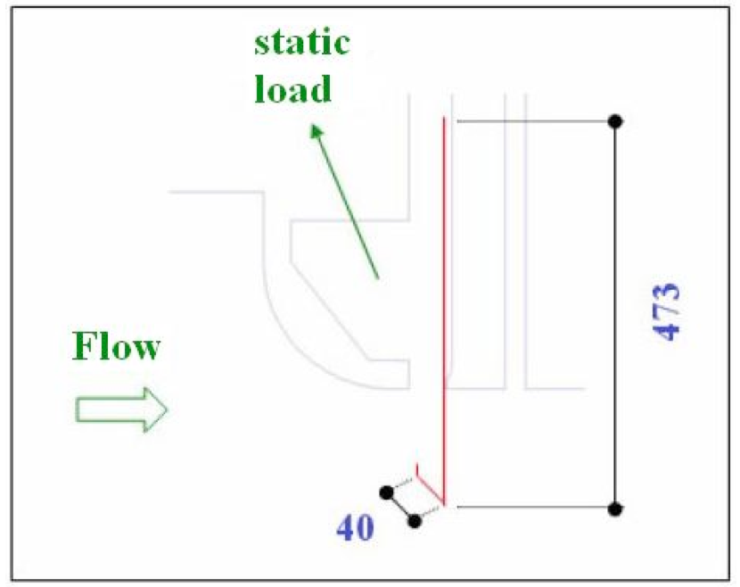
Fig. 3 Detail of the radial stoplog gate of the numerical model.
Some considerations were made in building the geometry of numerical model; the first is not building the upper curve of type section tunnel. This numerical model allows the use of a boundary condition of symmetry in their longitudinal section, thus the upper curve would be very low, consequently not having significant area to change any value in the calculation of the flow. The second consideration is the presentation of radial stoplog gate. The numerical model shows the floodgate by the plate of vestment, knife and horizontal beam. This conception facilitates the domain discretization (mesh generation) in the region, without compromising the reading of hydrodynamic efforts acting on the same, because loading into the upstream region is considered as static. The floodgate of numerical model and their principal dimensions, in millimeters, are shown in Figure 3.
With the definition of geometry of the problem, called domain, it is defined the region of interest in which the simulation is performed, the following procedure describes the boundary conditions.
The boundary conditions are the physical characteristics considered in the border of domain, representing the interaction of it with the rest of the universe, thus, seeking to establish possible closer relations with the physical reality of the problem.
In reduced physical models, the interpretation of the boundary conditions should be analyzed with caution, because errors as pressure drop (by using valves) or roughness of the used materials can introduce errors in reading the values, the same is applicable for the geometric tolerances. These controls present- reveal the rigidity of physical model when compared with prototype model.
For the numerical model of the Machadinho HPP (Bardella, 1999), five boundary conditions and the geometries were defined, illustrated in Figures 4 and 5, respectively.
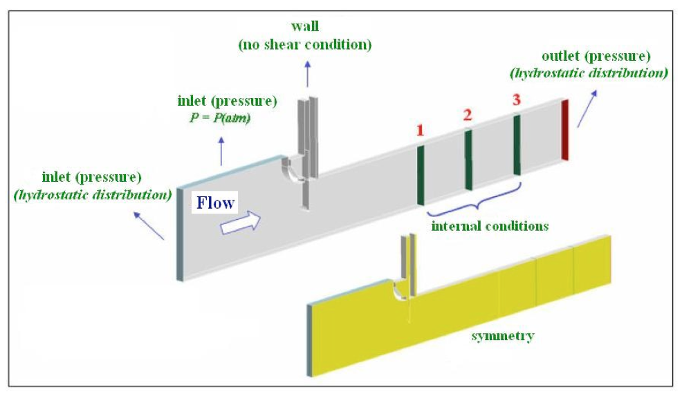
Fig. 4 Boundary conditions applied to the three dimensional numerical model.
-----
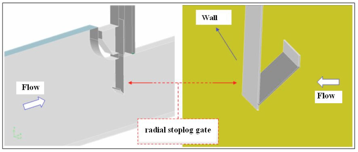
Fig. 5 Geometry detail of radial stoplog gate of numerical model.
Inlet: face of the domain where is inserted into the input condition of the drainage. The fluid flows only into the domain. In the proposed model, this condition is utilized in two situations: the vertical position in the left side, where a pressure gradient with hydrostatic distribution (in relation to the y axis) is established, and the horizontal position on the upper side by the upstream of the reservoir. With the value of the pressure equal to zero, it characterizes the surface of the reservoir as submitted to atmospheric pressure.
Outlet: the side of the domain where the fluid flows only outward. The condition utilized in the vertical position in the domain output, where the actual drainage establishes the pressure gradient with hydrostatic distribution.
Wall: side of the domain that represents impermeable condition for drainage. Type 1 was considered as not having resistance; this condition was utilized in the two upper horizontal sides of the grooves of the radial stoplog gate and the radial shut off gate, respectively. Type 2, characterized as a rough wall, was utilized for the other sides of the domain that did not receive their own boundary conditions.
Symmetry: side of the domain where the drainage is symmetrical so that the gradient of the normal variables by the side are null. Thus, the drainage of one side of the plane is a mirror image of the other side. This boundary condition has been applied throughout all model (xy plane in the z direction), thus allowing to simulate mid-span.
Interiors: the only condition applied on the internal sides of the domain, not altering any property of the drainage. The utilization of this boundary condition is necessary to connect the geometric volumes constructed, in addition to enable the reading and monitoring of physical properties during the calculation process.
For numerical simulations the software FluentTM version 6.1.22 was used, which utilizes the finite volume method to solve drainage. For the mesh generation and definition of boundary conditions on the sides of the domain, the software Gambit version 2.4.6 applied.
The computer utilized for the analyses was an Intel XeonÒ, composed of a nucleus with four 3.20 GHz processors with 16 GB of RAM memory. The water properties adopted were: r = 998.2 kg/m3, m = 0.001 kg/m.s and g = 9.806 m/s2.
For the numerical model, we utilized the implicit formulation, with the segregation simulator, where the equations to solve each component of velocity are separately calculated in relation to pressure.
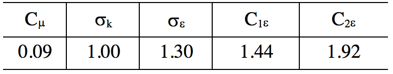
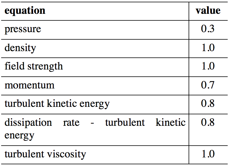
The SIMPLE (Semi-Implicit Method for Pressure Linked Equations) algorithm (Patankar, 1972) was utilized to solve the coupling of the field of pressure and velocities. To calculate the amount of movement, kinetic energy and dissipation rate of turbulence, it was utilized the upwind first order scheme. To obtain the turbulent kinetic energy and respective dissipation, the k–e turbulence model was used (standard), their coefficients shown in Table 1. The wall function, also the standard type, was employed to solve the drainage in the viscous sub-layer of the boundary layer. Table 2 shows the sub-relaxation coefficients utilized to solve the numerical models proposed.
Table 1. Coefficients of the k-e turbulence model.
-----
Table 2. Sub-relaxation coefficients
utilized for numerical models.
We utilized the standard convergence criterion of the FluentTM software to solve the system of equations, utilizing the Gauss-Seidel method in conjunction with a multigrid method for acceleration of convergence (FluentTM, 2003).
Here, was compared the theoretical results, the results obtained in reduced physical models and the results of the three dimensional numerical model, for the diversion tunnel of the Machadinho HPP.
The analytical calculation of hydrodynamic forces acting in radial gates is a task that requires a series of geometric considerations. These considerations are explained by the numerous configurations adopted in project design, where each equipment is sized according to the characteristics of the construction and its utilization.
Thus, it is not always possible to find directly in tables and graphs the values corresponding to the unknowns; as a consequence, the analytical results generally have more conservative values or require tests in a reduced physical model to prove these results.
As an example of theoretical calculation, it considers the radial stoplog gate of the diversion tunnel from the Machadinho HPP, which is subjected to a hydraulic head (H) of 21 [m]. The geometric configuration of the knife shown in Figure 6 was subject of investigation.
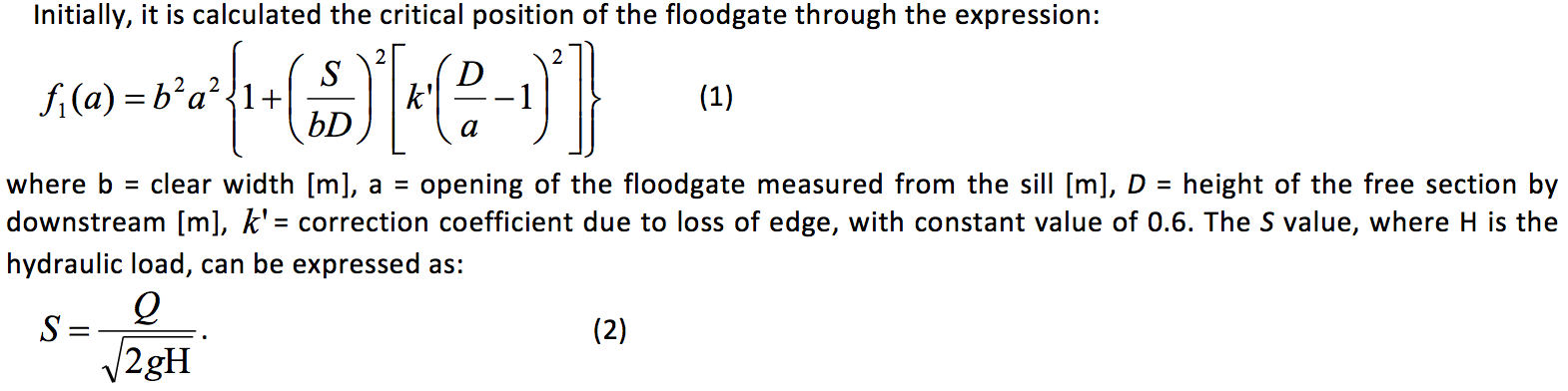
Thus we must assign the proper numerical values (see Figure 6) to the above two equations, respectively:
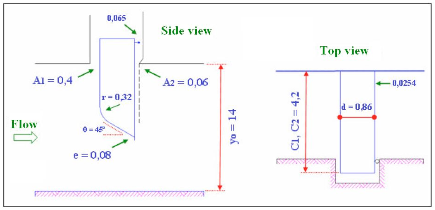
Fig. 6 Geometry considered for the application example.
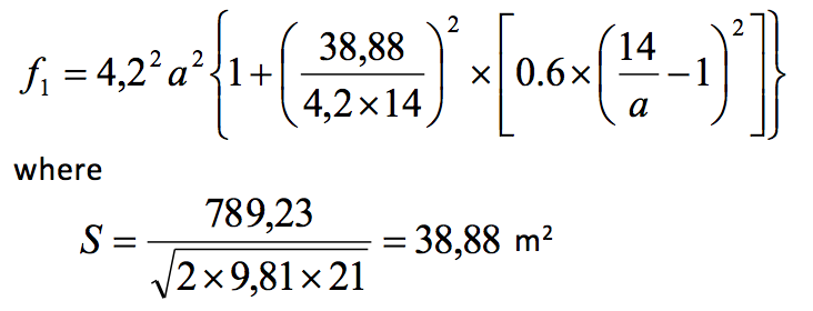
Figure 7 shows the graph of values of critical opening, and their location can be determined by the expression:
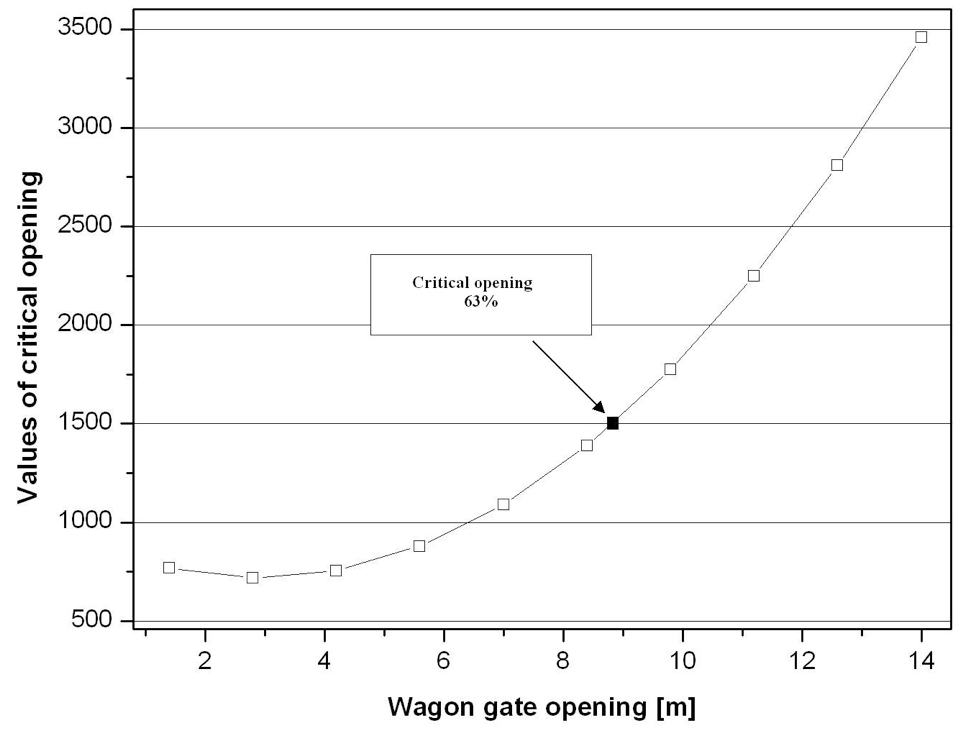
Fig. 7 Graph of values of critical opening and its location.
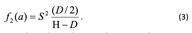
For values above the critical opening, the expression is applied to the recalculation of the flow and corresponding velocities, shown in Table 3.
Table 3. Calculation of flow and velocity for critical opening.
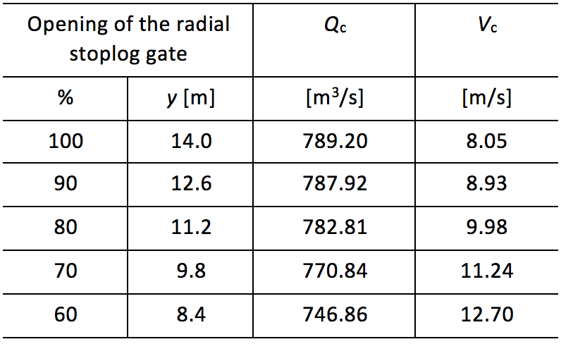
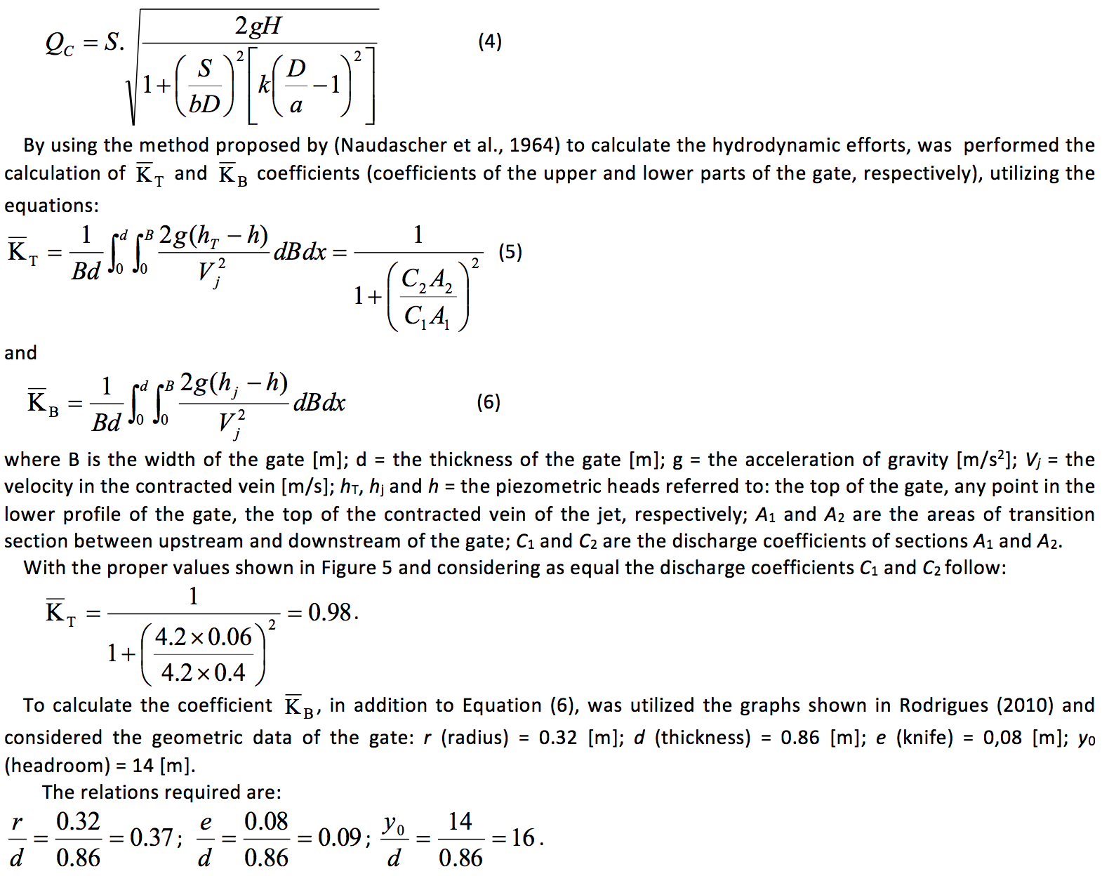
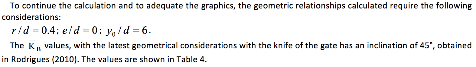
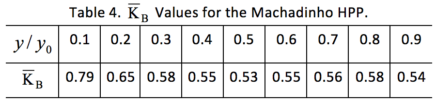
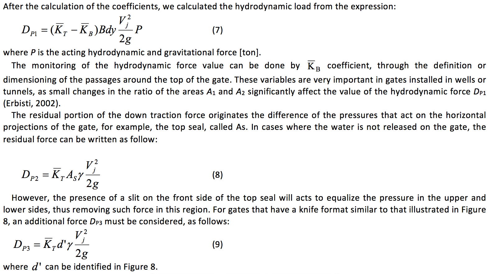
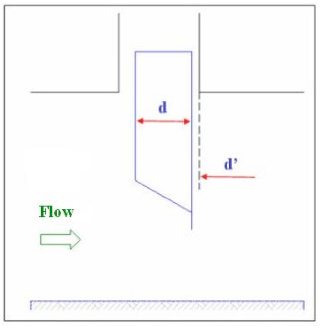
Fig. 8 Arrangement of a possible lower knife for radial gates.
Table 5 shows the values of the hydrodynamic forces acting on the radial stoplog gate calculated by the method of (Naudascher et al., 1964).
Table 5. Hydrodynamic force values acting on the Machadinho HPP.
Regardless of the hydrodynamic force value presented by the method, we found that the greater efforts acts in the 30-50% openings. For this range of hydrodynamic efforts, four tests carried out through the reduced physical model (Rodrigues, 2010).
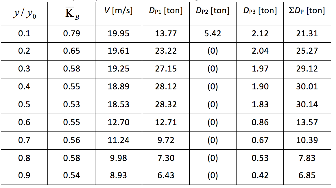
Table 6 shows the theoretical results of the hydrodynamic efforts, together with the results obtained with the reduced physical model and with the numerical results.
The analysis of the data presented in Table 6 shows that the numerical model reproduced the curve of the hydrodynamic efforts of the reduced physical model. The average difference between the values is approximately 7%, within an acceptable range (Rodrigues, 2010), taking into account the difficulty to correctly interpret the hydrodynamic forces.
Table 6. Hydraulic efforts value by theoretical methods, reduced
physical model and numerical model of the Machadinho HPP.
The present study demonstrated the possibility of utilizing a CFD commercial package to determine the hydrodynamic efforts that act on radial stoplog gates (of hydroelectric plants) installed inside the diversion tunnels excavated in rock.
The results of the three-dimensional numerical models, generated for each opening of the radial stoplog gate, reproduced the hydraulic phenomena observed in laboratory. The numerical results showed an average difference of 7% for hydrodynamic force in relation to experimental tests.
The differences are in an acceptable range (Rodrigues, 2010), once that even the tests on physical models, recognized by the generation of more reliable results, implies in errors like: pressure drop at the entrance of the upstream reservoir, roughness of the materials utilized or even geometric tolerances.
The reliability of the applied numerical methodology allows the extrapolation to other tests for diversion tunnels, with the obvious attention to the hydraulic and geometric characteristics of the prototype.
The utilization of numerical models for this purpose is an important tool for engineering, reflecting directly in projects and reducing costs, both determining the lifting mechanism and in the significant reduction in laboratory tests, also providing a shorten time for analysis of the results.
Bardella S.A. Indústrias Mecânicas. Túnel de Desvio da UHE Machadinho, Relatório de Ensaio em Modelo Físico nº 80.8707.41_REV.1, 1999.
Centro Tecnológico de Hidráulica (CTH), CAPANDA – Complexo Hidrelétrico Túnel de Desvio – Comporta Vagão – Estudo em Modelo Reduzido – Escala 1:25, 3 Volumes, Catalogação RT00470, 71 e 72, 1988.
Erbisti, P. C. F. Comportas Hidráulicas. 2ª ed. Rio de Janeiro, 2002. (in portuguese)
Fluent 6.1TM., User´s Guide, Fluent Inc., 2003.
Kuiyi Zhou. Water Conservancy Technology. A History of Chinese Science and Technology
pp 349-404, 2014.
Motta, V. F.. Curso de teoria da semelhança. Porto Alegre, Universidade Federal do Rio Grande do Sul, 1972. (in portuguese)
Naudascher, E., Kobus, H. E. e Rao, R. P., Hydrodynamic Analysis for High-Head Leaf Gates, Paper nº 3904, Journal of the Hydraulics Division, Proceedings of ASCE, vol. 90, HY3, may 1964.
Patankar, S. V.; Spalding, D. B., A calculation Procedure for Heat, Mass and Momentum Transfer in in Tree-dimensional Parabolic Flows, Int. J. Heat Mass Transfer, Vol 15, 1972.
Sarasúa J.I, Elías P., Martínez-Lucas G., Pérez-Díaz J.I., Wilhelmi J.R., Sánchez J.A.. Stability Analysis of a Run-of-River Diversion Hydropower Plant with Surge Tank and Spillway in the Head Pond. The Scientific World Journal Volume 2014 (2014), Article ID 874060, 13 pages http://dx.doi.org/10.1155/2014/874060
SUN Bin,,Lü Hong-xing, ZHANG Kuan-di, SHI Xi1,DINH Thi Huong,ZHOU Ya-sen. Numerical simulation and experimental research of hydraulic jumps on the airfoil-shaped measuring flume in U-shaped canal. Journal of Experiments in Fluid Mechanics, 2013.
Tao Wanga, Hegao Wua, Yang Lia, Huizhong Guic, Yong Zhoua, Ming Chena, Xiong Xiaoa, Weibo Zhoua, Xianyu Zhaoa, Stability analysis of the slope around flood discharge tunnel under inner water exosmosis at Yangqu hydropower station. Computers and Geotechnics, Volume 51, June 2013, Pages 1–11.
Rodrigues, A. C.. Simulação Numérica do Escoamento sob a Comporta de um Túnel de Desvio de Alex Cristiano Rodrigues. Usina Hidrelétrica. Tese de Doutorado, UNICAMP-Brazil, 2010. (in portuguese).
1. State University of Campinas, Mechanical Engineering Faculty, Thermal and Fluids Engineering Department, Campinas, São Paulo
2. Department of Basic and Environmental Sciences, Lorena School of Engineering, University of São Paulo-USP, Lorena/SP, Brazil. Email: estaner23@usp.br
3. State University of Campinas, Mechanical Engineering Faculty, Thermal and Fluids Engineering Department, Campinas, São Paulo
4. State University of Campinas, Mechanical Engineering Faculty, Thermal and Fluids Engineering Department, Campinas, São Paulo