![]() ISSN 0798 1015
ISSN 0798 1015

![]() ISSN 0798 1015
ISSN 0798 1015
 Vol. 40 (Number 29) Year 2019. Page 8
ORTIZ-CASTRILLÓN, José R. 1; JARAMILLO-DUQUE, Álvaro 2; MUÑOZ-GALEANO, Nicolás 3; SIERRA-AGUILAR, Juan E. 4 & LOPEZ-LEZAMA, Jesús M. 5
Received: 12/04/2019 • Approved: 13/08/2019 • Published 02/09/2019
ABSTRACT: In this paper, a unified method for calculating variables and parameters of transformers considering power losses in their windings is proposed. This method presents an educational tool for teaching how to obtain the steady-state operating conditions of transformers used to make technical and economic decisions. Five variants are considered in calculations using single-phase, three-phase or per-unit (p.u) equations. This method is validated by calculations and simulations (ATPDraw); also, an on-line PYTHON graphic interface was implemented. |
RESUMEN: En este artículo se propone un método unificado para calcular las variables y parámetros de transformadores considerando pérdidas de potencia en sus devanados. Este método presenta una herramienta educativa para enseñar a obtener las condiciones operativas de transformadores en estado-estable usadas para tomar decisiones técnicas y económicas. Se consideran cinco variantes para los cálculos usando ecuaciones monofásicas, trifásicas y por-unidad (p.u). Este método se valida con cálculos y simulaciones (ATPDraw); además, se implementó una interfaz gráfica on-line en PYTHON. |

Transformers in electrical systems are used as a link between generation and transmission, as well as transmission and distribution, and distribution and final users. The main function of transformers in transmission systems consist on increasing the voltage magnitude for reducing electric losses in the lines. In distribution systems, transformers are commonly used for decreasing voltage magnitude up to operation levels and feeding electric devices minimizing security risks for people. In addition, transformers have windings with galvanic isolation and power transference is given by means of electromagnetic induction, providing isolation between electrical systems; in consequence, the transformer protection is essential for electrical grids (Vahidi & Esmaeeli, 2013), (Varan & Yurtsever, 2017). Transformers are also used for improving power quality, controlling angle-phase (Thompson, Miller, & Burger, 2008), starting motors (Huan, Xiangrui, & Guangzhe, 2012), and filtering third order and zero sequence harmonics (Ionescu, Paltanea, & Paltanea, 2013), (Hurng-Liahng, Kuen-Der, Jinn-Chang, & Wen-Jung, 2008).
Network operators need to know transformers operating conditions due to technical and economic reasons (Xiao-pin, Yi-yi, Yue, & Bin, 2014), (Georgilakis & Amoiralis, 2010). Transformer variables such as feeding voltage, output voltage, currents and load data are used in reliability studies, overload voltage regulation, disconnections and circuit transferences (Yazdani-Asrami, Mirzaie, & Shayegani Akmal, 2010). Hence, electrical engineers and students of electrical engineering need a methodology for learning how to find the transformer variables and parameters.
Generally, the conventional model is used for studying the transformer behavior in steady state (Jiale, Jiao, Song, & Kang, 2009). The conventional model is based on the transformer equivalent circuit where its windings are represented as inductors with resistances connected in series and the transformer core is represented as an inductor with a resistance connected in parallel. Nevertheless, the conventional model is modified according to the study to be done, for example: the high frequency model is formed adding to the conventional model the capacitive couplings between its windings. This model is used for designing transformers for isolation and voltage impulse tests (Nagy & Osama, 2010). The conventional model is combined with the transformer magnetic model for analyzing inrush currents in the magnetization branch (Abdulsalam, Xu, & Dinavahi, 2005). On the other hand, the conventional model is adapted to the RLC model when it is necessary to study transformer responses due to transient states (Hassan Hosseini, Vakilian, & Gharehpetian, 2008), (Yang, Wang, Cai, & Wang, 2011), (Celis-Montero, Castro-Aranda, & Martinez-Velasco, 2012), (Vahidi, Agheli, & Jazebi, 2012).
In this paper, the transformer solution method is deduced in steady state from a simplified model based on the conventional model. The main contribution of this paper consists on providing an educational tool for students of electrical engineering and electrical engineers regarding the solution of the transformer simplified model. The proposed solution allows obtaining voltages, currents, powers, power losses, efficiency, voltage regulation and power factor by means of nominal characteristics (transformer identification plate), test results (Ayasun & Nwankpa, 2006) and load connected. The proposed method has five variants: 1) single-phase solved from transformer primary side, 2) single-phase solved from transformer secondary side, 3) three-phase solved from transformer primary side, 4) three-phase solved from transformer secondary side and 5) per unit solution. Each variant can be applied according to the windings connection (wye or delta).
This paper is organized as follows: Section 1 presents the transformer conventional model based on power losses and the use of the simplified model is justified; in section 2, the solution method with its five variants is described; Section 3 presents the method validation through mathematical calculations and simulation in ATPDraw; in Section 4, the graphic interface for solving three-phase transformers is shown; finally, in section, 5 the most relevant conclusions and discussions are presented.
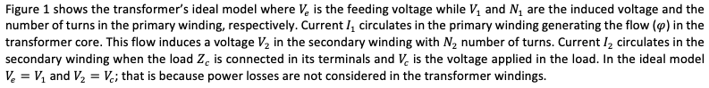
Figure 1
Transformer’s
ideal model
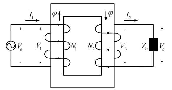

Figure 2
Transformer model
based on losses

Figure 3
Transformer conventional
model.
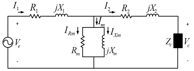

Figure 4
Transformer
simplified model
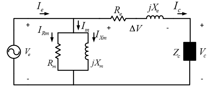
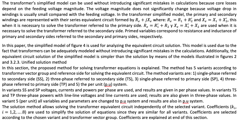
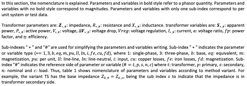
Table 1
Parameters and variables according to variant selected
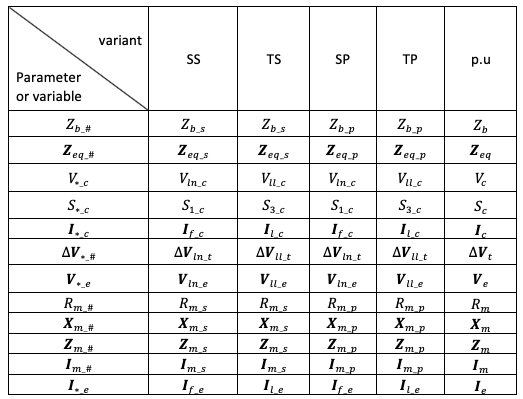
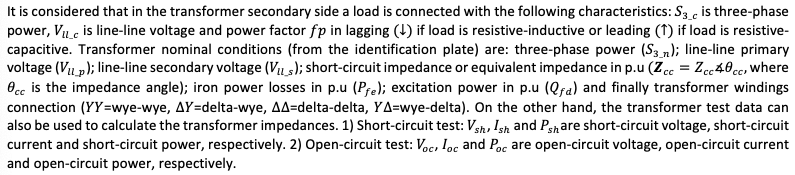
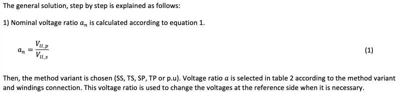
Table 2
Voltage ratio a
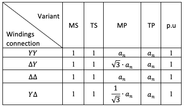
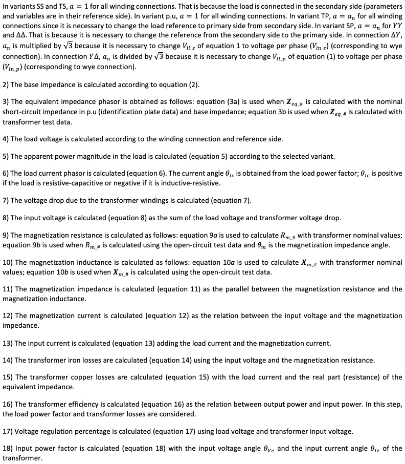
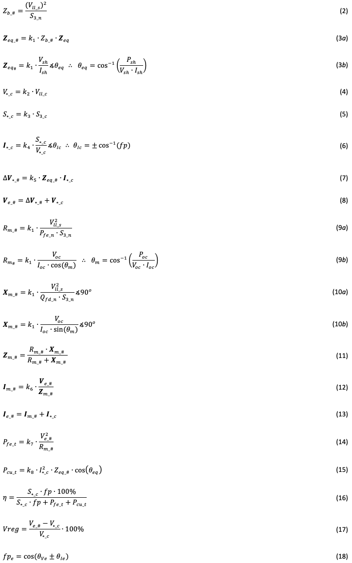
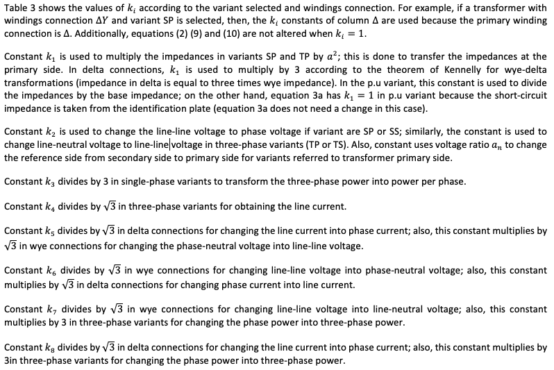
Table 3
Constants k_i according to method variant
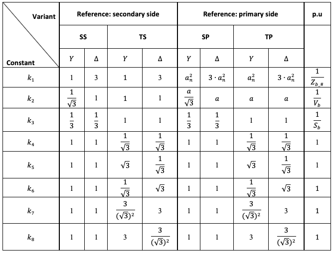
Figure 5
Circuit to simulate
in ATPDraw
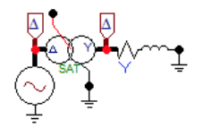
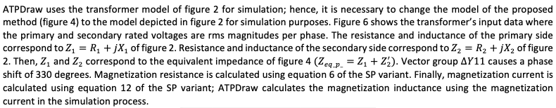
Figure 6
Input data for
ATPDraw simulation
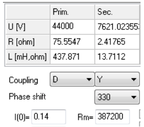
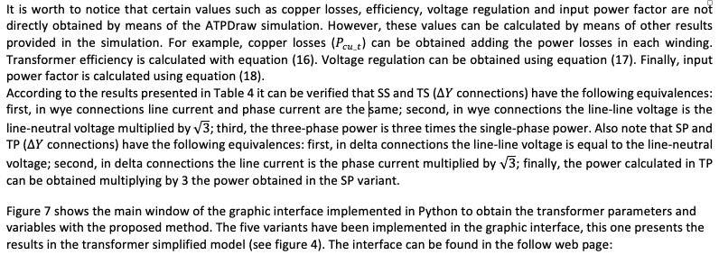
Table 4
Results of
proposed method
https://github.com/IceMerman/TransformerSolution

Figure 7
Graphic interface
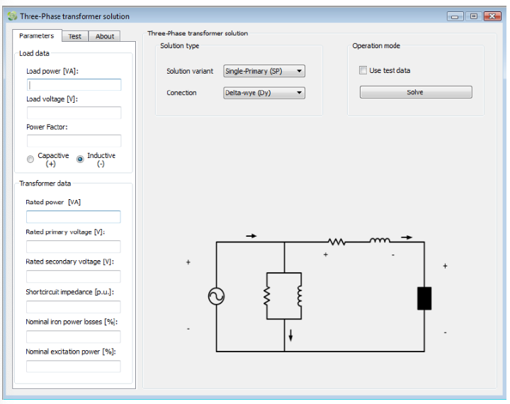

Figure 8
Test data panel of
the graphic interface
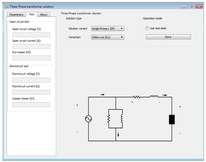

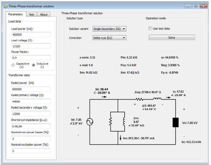
Figure 9
Calculation results
for SS variant
In this paper, a method with five variations to solve the equivalent circuit of three-phase transformers was proposed and explained. This method allows calculating the electric variables (voltages, currents, powers, efficiency, power factors and voltage regulation) of transformer according to load condition, transformer parameters and transformer test data. The proposed method uses the simplified transformer model and was validated by means of simulations in ATPDraw. Despite of the fact that ATPDraw uses a different transformer model, simulation results were equivalent.
Mathematical results and simulations demonstrate the equivalence between the five method variants. Therefore, it is possible to present a general method to find the transformer variables. The application of the method is useful for engineers in making technical and economic decisions regarding transformer selection and its related variables; as well as for students for the understanding of transformers’ performance.
The results obtained with the graphical interface implemented in PYTHON were consistent with the simulations performed in ATPDraw. In this interface, students as well as engineers can obtain the transformer parameters and variables entering the load characteristics, the transformer data from the identification plate and the results of short-circuit and open-circuit tests.
Abdulsalam, S. G., Xu, W., & Dinavahi, V. (2005). Modelling and simulation of three-phase transformers for inrush current studies. IEE Proceedings - Generation, Transmission and Distribution, 152(3), 328–333. https://doi.org/10.1049/ip-gtd:20041060
Ayasun, S., & Nwankpa, C. O. (2006). Transformer tests using MATLAB/Simulink and their integration into undergraduate electric machinery courses. Computer Applications in Engineering Education, 14(2), 142–150. https://doi.org/10.1002/cae.20077
Celis-Montero, J. E., Castro-Aranda, F., & Martinez-Velasco, J. A. (2012). Modelo práctico del transformador de distribución trifásico para análisis de transitorios de baja frecuencia: Identificación de parámetros. Ingeniare. Revista Chilena de Ingeniería, 20, 293–303.
Georgilakis, P. S., & Amoiralis, E. I. (2010). Distribution transformer cost evaluation methodology incorporating environmental cost. IET Generation, Transmission & Distribution, 4(7), 861–872. https://doi.org/10.1049/iet-gtd.2009.0638
Hassan Hosseini, S. M., Vakilian, M., & Gharehpetian, G. (2008). Comparison of Transformer Detailed Models for Fast and Very Fast Transient Studies. IEEE Transactions on Power Delivery, 23(2), 733–741. https://doi.org/10.1109/TPWRD.2008.915795
Huan, W., Xiangrui, S., & Guangzhe, J. (2012). The study of switch transformer medium voltage asynchronous motor soft-start device. Power Electronics and Motion Control Conference (IPEMC), 2012 7th International, 4, 2422–2425. https://doi.org/10.1109/IPEMC.2012.6259235
Hurng-Liahng, J., Kuen-Der, W., Jinn-Chang, W., & Wen-Jung, C. (2008). A Three-Phase Four-Wire Power Filter Comprising a Three-Phase Three-Wire Active Power Filter and a Zig–Zag Transformer. IEEE Transactions on Power Electronics, 23(1), 252–259. https://doi.org/10.1109/TPEL.2007.911779
Ionescu, G., Paltanea, G., & Paltanea, V. (2013). A method for minimization the harmonic distortions in three-phase inverter devices. Advanced Topics in Electrical Engineering (ATEE), 2013 8th International Symposium On, 1–4. https://doi.org/10.1109/ATEE.2013.6563380
Jiale, S., Jiao, Z., Song, G., & Kang, X. (2009). Algorithm to identify the excitation inductance of power transformer with wye-delta connection. IET Electric Power Applications, 3(1), 1–7. https://doi.org/10.1049/iet-epa:20080037
Martínez-Velasco, J. A., & de León, F. (2011). Circuito equivalente de un transformador con regulación. Ingeniare. Revista Chilena de Ingeniería, 19, 93–109.
Nagy, A., & Osama, M. (2010). Physics-Based High-Frequency Transformer Modeling by Finite Elements. IEEE Transactions on Magnetics, 46(8), 3249–3252. https://doi.org/10.1109/TMAG.2010.2048017
Thompson, M., Miller, H., & Burger, J. (2008). Innovative power flow regulating tap-changer control installed on multiple phase-shifting transformers. Transmission and Distribution Conference and Exposition, 2008. T&D. IEEE/PES, 1–9. https://doi.org/10.1109/TDC.2008.4517270
Vahidi, B., Agheli, S. A., & Jazebi, S. (2012). Teaching short-circuit withstand test on power transformers to M.Sc. students and junior engineers using MATLAB-SIMULINK. Computer Applications in Engineering Education, 20(3), 484–492. https://doi.org/10.1002/cae.20416
Vahidi, B., & Esmaeeli, E. (2013). MATLAB-SIMULINK-based simulation for digital differential relay protection of power transformer for educational purpose. Computer Applications in Engineering Education, 21(3), 475–483. https://doi.org/10.1002/cae.20493
Varan, M., & Yurtsever, U. (2017). Multi-DGAS: A pattern based educational framework design for power transformers faults interpretation and comparative performance analysis. Computer Applications in Engineering Education. https://doi.org/10.1002/cae.21872
Xiao-pin, D., Yi-yi, Z., Yue, T., & Bin, L. (2014). A life cycle cost-effectiveness assessment model for power transformer selection based on grey correlation analysis. Electricity Distribution (CICED), 2014 China International Conference On, 1168–1173. https://doi.org/10.1109/CICED.2014.6991891
Yang, Y., Wang, Z. J., Cai, X., & Wang, Z. D. (2011). Improved lumped parameter model for transformer fast transient simulations. IET Electric Power Applications, 5(6), 479–485. https://doi.org/10.1049/iet-epa.2010.0114
Yazdani-Asrami, M., Mirzaie, M., & Shayegani Akmal, A. A. (2010). Investigation on impact of current harmonic contents on the distribution transformer losses and remaining life. Power and Energy (PECon), 2010 IEEE International Conference On, 689–694. https://doi.org/10.1109/PECON.2010.5697668
1. Master student. Department of Electrical Engineering. Research group of efficient energy management (GIMEL). University of Antioquia. jrobinson.ortiz@udea.edu.co
2. Ph.D. in Electronics and Automation. Department of Electrical Engineering. Research group of efficient energy management (GIMEL). University of Antioquia. alvaro.jaramillod@udea.edu.co
3. Ph.D. in Electronics. Department of Electrical Engineering. Research group of efficient energy management (GIMEL). University of Antioquia. nicolas.munoz@udea.edu.co
4. Master student. Department of Electrical Engineering.Figure 6. Input data for ATPDraw simulation. Research group of efficient energy management (GIMEL). University of Antioquia. juane.sierra@udea.edu.co
5. Ph.D. in Electrical Engineering. Department of Electrical Engineering. Research group of efficient energy management (GIMEL). University of Antioquia. jmaria.lopez@udea.edu.co