![]() ISSN 0798 1015
ISSN 0798 1015

![]() ISSN 0798 1015
ISSN 0798 1015
 Vol. 39 (Number 35) Year 2018. Page 6
Javier ROLDÁN Mckinley 1; Eugenio YIME Rodríguez 2; José SOSA Rodríguez 3
Received: 20/03/2018 • Approved: 10/05/2018
ABSTRACT: This paper describes the replacement of a manufacturer-provided closed architecture controller in a widely academic used robot: Movemaster RVM1. The original controller was replaced for five low cost in-house designed analog servoamplifiers. They are commanded by an analog input within the range ±10V to perform control of DC motors using PWM signals. These analog signals come from six 16-bit A/D ports integrated in a dSpace control card. dSpace was selected because of its easy integration with Matlab and Simulink, a de-facto standard in Robotics education. The new open architecture was tested with a gravity compensation control strategy for tool position. The satisfactory results of the control strategy implementation suggest the robot capability has been enhanced. In addition, further implementation of other serial manipulator control laws might be achieved. |
RESUMEN: Este artículo describe el reemplazo de un controlador de arquitectura cerrada suministrado originalmente por el fabricante para un robot ampliamente usado en la academia: Movemaster RV-M1. El controlador original fue reemplazado por cinco servoamplificadores análogos de bajo costo que fueron construidos en el laboratorio, comandados por una entrada análoga de rango ±10V para control de motores DC usando modulación del ancho de pulso. Estas señales análogas provienen de seis puertos de 16 bit tipo A/D, integrados en una tarjeta de control dSpace, escogida por su facilidad de integración con Matlab y Simulink, un estándar de-facto en la educación de la Robótica. La nueva estructura fue evaluada con una estrategia de compensación por gravedad para posición de la herramienta. Los resultados satisfactorios en la implementación de la estrategia de control sugieren que la capacidad del robot ha sido mejorada, permitiendo además la posterior implementación de diversas estrategias de control de manipuladores seriales. |

PC-based open robot control systems arise from the lack of flexibility in the most of “control-boxes” provided by the robot manufacturers. These “black-boxes” allow, in the most cases, point-to-point pick and place tasks with no possibility of testing nonlinear control strategies such as those commonly thought in a course of Robotics. Early works in this field report open architecture in order to allow teleoperation of robots from desktop or laptop computers via world-wide web (Goldberg, et al., 1995), and open architecture for manufacturing tasks (Fiedler & Schlib, 1998). A PUMA 560 robot was retrofitted with interface boards that allowed it to connect it to a standard PC with excellent tracking results (Costescu, et al., 1998), and generalized architecture proposals for PC open robots programming in industrial applications were made (Topper & Eng, 1991) with latter applications to SCARA (Hong, et al., 2001; González, et al., 2004), Movemaster-EX (Pan & Huang, 2004) and BOSCH SR-800 (Slawinski, et al., 2007) robots.
More recently, Farooq and Wang (2007) and Farooq, Wand and Dar (2007) integrated PC based (open architecture) controller for a real time control of the PUMA robot six joints, using pulse width modulation amplifiers and programming written in VC++. Implementation of open architecture xPC Target real time based robot controllers have been also done for industrial and research manipulators: Staubli RX-90 (Mihelj & Munih, 2010). xPC Target has been also used with FPGA I/O boards to interact with the controller of a RRR serial manipulator and outside environment (Pinzón-Ardila, Ángel & Useche, 2011), and even for real time control of the Stewart platform (Ordóñez & Rodríguez, 2012). Gámez et al. (2010) also implemented open architecture for an industrial robot, Staubli RX60, proving its advantage for testing sensor based concepts in robotics research, and more generalized and conceptual approaches have been proposed looking towards a generic and universal architecture design methodology for robotics manipulators (Hassan, et al., 2010; Short & Burn, 2011).
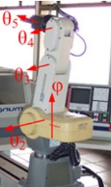
This report documents the integration of the dSpace 1103 controller card with in-house built signal adapters and servo-amplifiers to a Mitsubishi Movemaster RV-M1 manipulator, Figure 1, the most widely used manipulator in academia regardless its limited functionality (Kumar, Kalra & Prakash, 2011). It is vertical-type serial manipulator with five degrees of freedom, with five DC servomotors and 1.2 kg payload capacity (Mitsubishi Electric Corp., 1989). The primary goal of this project is to allow the testing of some type of nonlinear control including a future teleoperation of the robot, in order to strength the teaching of robotics in academia and industry with this manipulator beyond the typical kinematic point-to-point interface (Świder, et al., 2007; Foit, 2008). The hardware integration is tested with the gravity-compensation control law implementation.
Figure 1
Movemaster RV-M1 joints identification
Source: Own Elaboration
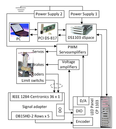
The original manufacturer controller for the RV-M1 is a black-box type one that allows only point-to-point task based on joint-to-joint control (linear). The scheme is depicted in Figure 2. The new architecture development is presented as follows. There are five analog servo amplifier cards to amplify the DC input voltage ranging from -10 V to 10 V coming from the dSpace 1103 card. The input signal is bounded to -10V to 10V, required for operation of the robot servomotors. The maximum current capability is 3 A. For the digital signals distribution it was required an adapter with an entry type IEEE 1284 Centronics-36-pin connector and five outputs (one per motor), each one is a serial connector type DB15HD-2Rows to be connected to the CP 1103 led panel. The connector also distributes the limit-switch and ground signals.
Five servo-amplifier cards were built to scale the DC control voltage signal (ranging from -10V to +10V) coming from the DS 1103 card, to the right value for the motor operation within the range [12, 24]V. It also changes the turn sense by changing motor polarity when the control signal changes. Five cards were built. Each card possesses three stages explained next.
Figure 2
Original configuration

Source: Own Elaboration
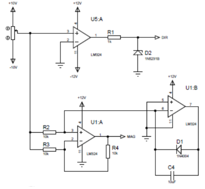
Control signal separation stage. At this stage, Figure 3, two data are extracted from the control signal. They are DC voltage magnitude and the direction or turning sense. The voltage magnitude is the absolute value of the control signal, MAG. The turning direction, DIR, is set as 0V for the negative sense (counter-clockwise), and +5V when the turning sense is along the opposite direction.
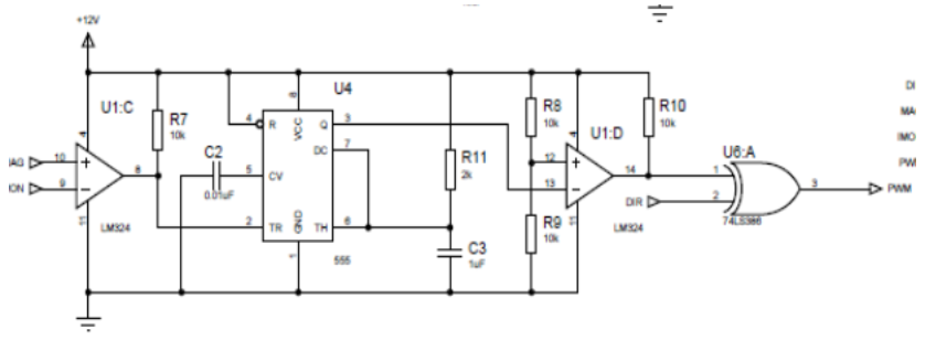
Pulse Width Modulation stage-PWM. At this stage, Figure 4, the integrated LM555 generates a pulses train with amplitude depends on the MAG signal value and from the current through the motor.
Voltage scaling and turning sense control stage. At this stage, Figure 5, the PWM signal reaches a 12VDC H-bridge circuit when active. The motor turning sense will depend on the DIR signal value. The current through the motor exits this stage as the IMOM signal.
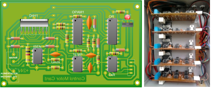
The components of the servo-amplifier card shown in Figure 6(a) are presented next.
DriH1: The H driver or bridge H is the power control integrated circuit.
OPAM1: It is the set of operational servo-amplifiers where the current motor flows through.
Figure 3
Control signal separation

Source: Own Elaboration
-----
Figure 4
PWM generation stage
Source: Own Elaboration
OR: It is the integrated circuit for the H driver control with PWM output signal.
TEMP: It is a timer that controls the PWM frequency sent to the motors.
DIR: It is an operational servo-amplifier where the motor turning sense is obtained from the analog signal.
ISEN: It is an operational amplifier to adjust the maximum current level for the motors. It was set 3A. Figure 6(b) depicts the five servo-amplifier cards disposition in the power box.
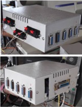
A signal adapter box was built from scratch. The digital signals are taken from the robot RV-M1 through a IEEE 1284/Centronics-36pin, as indicated in the schematic in Figure 7. The signals are distributed from the IEEE 1284 to five serial connectors DBH15HD-2 rows, one connector for each motor. The connector also uses the ground pin and the limit switch sensors of each robot, required for the homing procedure (or zero joint angle position). Figure 8 shows the built signal box aspect.
Figure 5
Voltage scaling and turning sense control
Source: Own Elaboration.
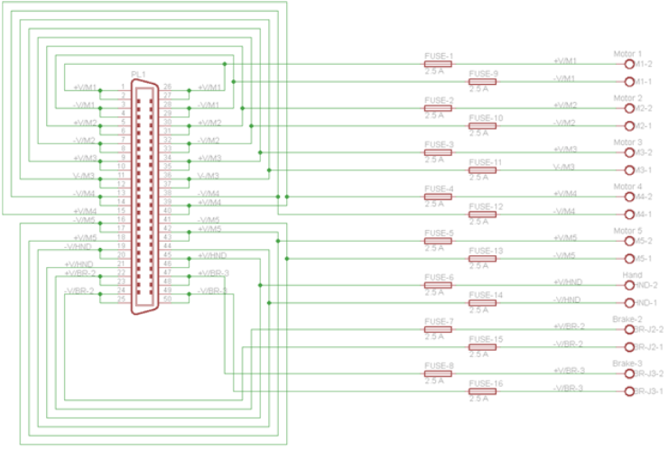
Mitsubishi RV-M1 power output is through a Centronics-50 pin x 2 row connector, as shown in Figure 9(a). It was also constructed the cable-connector for the power of the five servomotors. In addition, the cable also carries the power for the robot hand, and the brakes for the shoulder and the arm, labeled as M2 and M3 in the Figure 9(b) schematic.
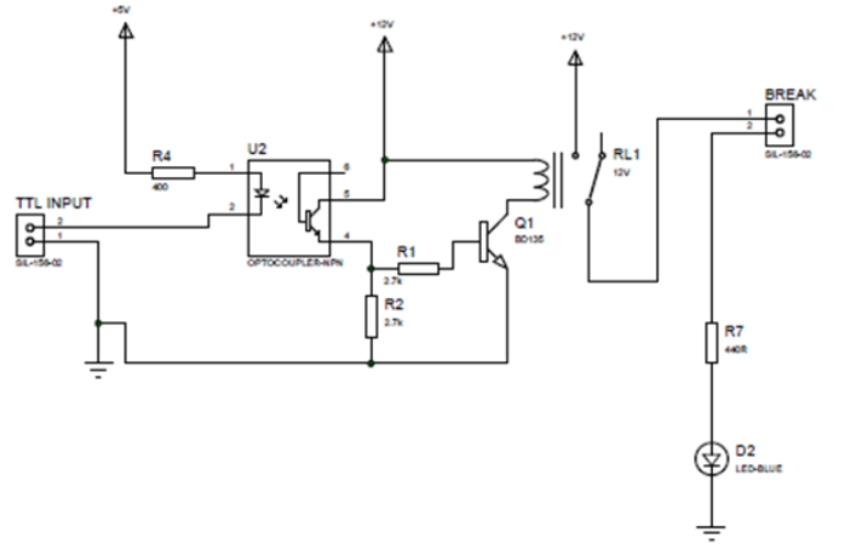
Motors 2 and 3 for the shoulder and arm, respectively, are labeled as terminals Brake-2 and Brake-3 in the schematic of Figure 9(b). Each brake is activated with a digital signal from the DS1103 dSpace card through a servo-amplifier card. This circuit, shown in Figure 10, isolates the input current to protect the DS1103 card with an optocoupler circuit. Brake-2 and Brake-3 are normally closed and deactivated when the zero value 0 enters port 2.
Figure 6
Printed circuit for the servo-amplifier card
Source: Own Elaboration.
Figure 11 presents the final disposition for the whole system.
Figure 7
Signal adapter schematic: IEEE1284(x1) to DB15HD-2 row (x5)
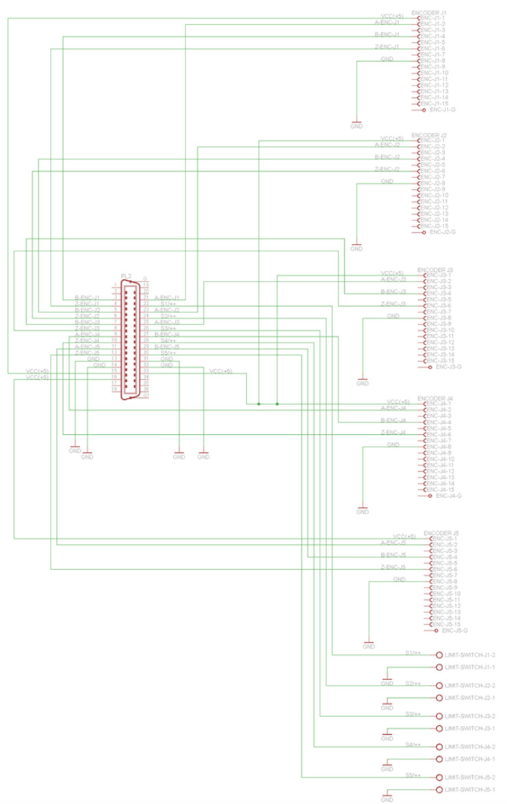
Source: Own Elaboration.
------
Figure 8
Signal boxes
Source: Own Elaboration.
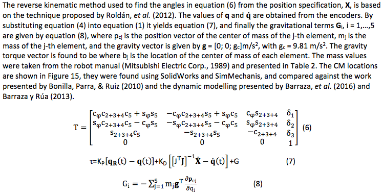
Figure 9
Integrated power distribution connector
(a) Robot power connector

(b) Power distribution connector
Source: Own Elaboration.
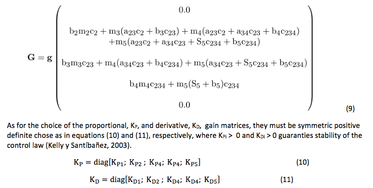
Figure 10
Brake timing card with circuit with optocoupler circuit
Source: Own Elaboration.
-----
Figure 11
New architecture of the robot
Source: Own Elaboration.
------
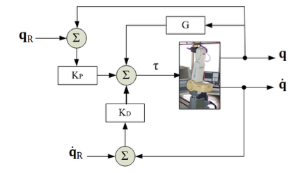
Figure 12
PD gravity compensation control law
Source: Own Elaboration.
-----
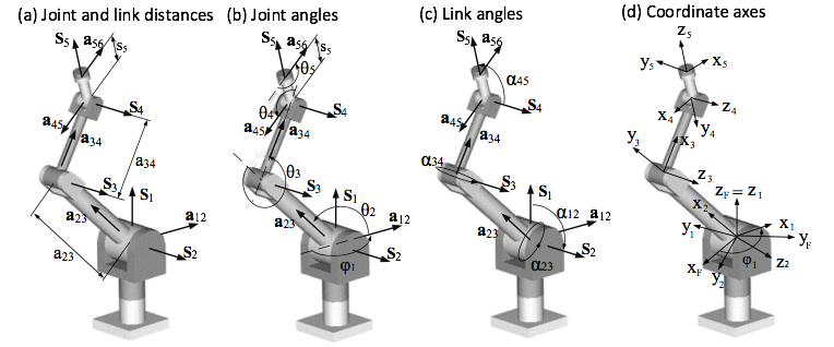
Figure 13
Crane & Duffy parameters [24] for the Movemaster RV-M1
Source: Own Elaboration.
-----
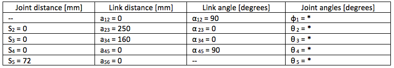
Table 1
Kinematic parameters of the Mitsubishi RV-M1 manipulator [18]
------
Figure 14
Mitsubishi RV-M1 lengths 1
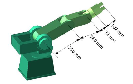
Source: Own Elaboration
-----
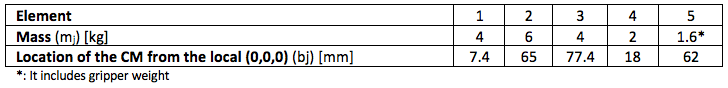
Table 2
Dynamic parameters of the Mitsubishi RV-M
-----
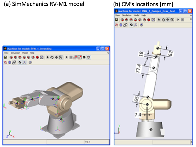
Figure 15
Mitsubishi RV-M1 lengths 1
Source: Own Elaboration.
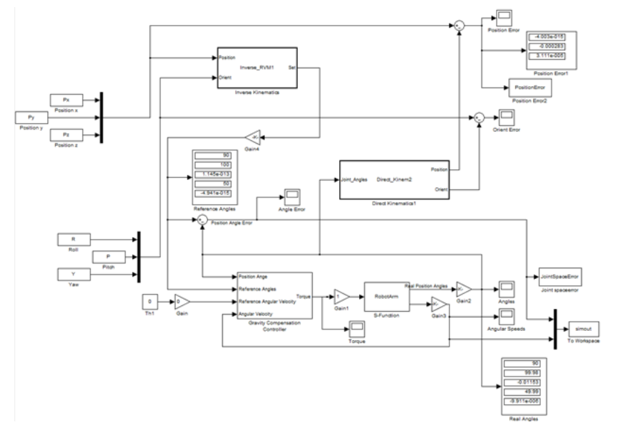
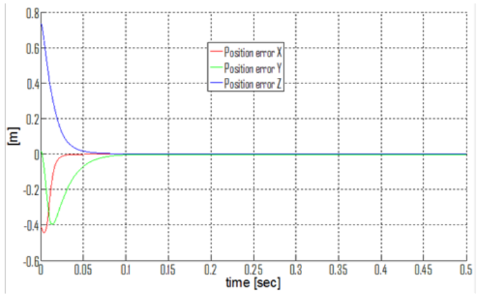
A trajectory that is typical of interior painting of spherical surfaces, shown in Figure 16, was chosen as the kinematic task to exemplify. The simulation was run with a Simulink model, Figure 17. The proportional and derivative matrixes used are KP = diag([30, 28, 20, 20, 4])*1000 N m/rad and KD = diag([3,5,7,5,3]*100) N m s/rad. The workspace position results are shown in Figure 18. After the implementation in the real robot with th open architecture, the real workspace position errors are shown in Figure 19. The steady state position error was found to be within 0.3 mm, considered satisfactory. However, further tuning of KP y KD might decrease this value.
Figure 16
Mitsubishi RV-M1 lengths 1

Source: Own Elaboration.
-----
Figure 17
Simulink model for the gravity compensation law of the RV-M1 robot
Source: Own Elaboration
-----
Figure 18
Simulation workspace position errors
Source: Own Elaboration.
-----
Figure 19
Real test workspace position errors, in meters, using dSpace
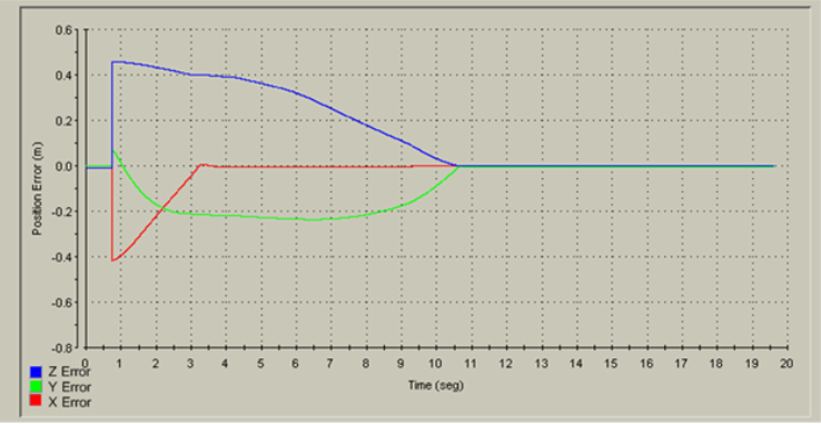
Source: Own Elaboration
The gravity compensation control method used in this paper is a simple scheme that allows dynamic position control of a vertical type manipulator, as the RV-M1. The method works well if all the exact dynamic robot parameters are known. However, the dynamic parameters of the Movemaster RV-M1 of Universidad del Atlántico might have some differences with respect to the standard parameters due mainly to the effect of aging. The joints friction and its loosing might have increased with time, adding further to the position error and justifying part of the difference between simulation and real test. Additional work for the tuning of the proportional and derivative gains might alleviate this problem. From the academic standpoint, the hardware integration and setup will allow future implementation of many basic dynamic control strategies, for both position and trajectory. This will also add towards the completion of the main long term goal which is a teleoperation laboratory for testing different manipulator control laws.
The authors acknowledge the support from RENATA-COLCIENCIAS Grant 487, Contract 562 (Colombia) and the support of Research Vice-Rectory at Universidad del Atlántico (Barranquilla, Colombia).
Barraza, A., y Rúa, J. (2013). Modelado dinámico realista del manipulador Mitsubishi Movemaster RV-M1. (Tesis de Pregrado). Universidad del Atlántico. Barranquilla, Colombia.
Barraza, A., Rúa, J., Sosa, J. Díaz, J. Yime, E., y Roldán J. (2016). Modelado dinámico del manipulador serial Mitsubishi Movemaster RV-M1 usando SolidWorks. Revista UIS Ingenierías, 15(2), 49-62.
Bonilla, M., Parra, V., & Ruiz, F. (2010). H2ILco-simulation of cooperative robots based on ADAMS, Matlab and a haptic interface. In Congreso Annual 2010 de la Asociación de México de Control Automático. Puerto Vallarta, Jalisco, México.
Costescu, N., Loffler, M., Zergeroglu, E., & Dawson, D. (1998). Q-Robot-A multitasking PC based robot control system. In IEEE International Conference on Control Applications (pp. 892-896). Trieste, Italy.
Crane, C., & Duffy, J. (2008). Kinematic Analysis of Robot Manipulators. New York, USA: Cambridge University Press.
Farooq, M., & Wang, W. (2007). A new Approach to implementation of an open architecture controller for a PUMA robot. In World Congress on Engineering and Computer Science-WCECS, San Francisco, USA.
Farooq, M., Wang, D., & Dar, N. (2007). Implementation of a new PC based controller for a PUMA robot. Journal of Zhejiang University SCIENCE A, 8(12), 1962-1970.
Fiedler, P., & Schlib, C. (1998). Open architecture robot controllers and workcell integration. Robotics Today, 11(4), 1-4.
Foit, K. (2008). Remote programming of the Mitsubishi Movemaster robot by using the web-based interface. Journal of Achievements in Materials and Manufacturing Engineering, 31(2), 639-645.
Gámez, J., Gómez, J., Sánchez, A., & Torres, S. (2010). Open software architecture for advanced control of robotics manipulators in non-structured environments”, In IEEE Int. Conf. on Robotics and Automation-ICRA (pp. 7-14). Anchorage, USA.
Goldberg, K., Mascha, M., Gentner, S., Rothenberg, N., Sutter, C., & Wiegley, J. (1995). Desktop teleoperation via the world wide web. In IEEE International Conference on Robotics and Automation (pp. 654-659). Nagoya, Japan.
González, J., Baeyens, E., Gayubo, F., Pérez, J., Fraile, J., y García, F. (2004). Desarrollo de un controlador abierto para un robot industrial tipo SCARA. Revista Iberoamericana de Automática e Informática Industrial, 1(1), 44-49.
Hassan, S., Anwer, N., Khattak, Z., & Yoon, J. (2010). Open architecture dynamic manipulator design philosophy (DMD). Journal of Robotics and Computer-Integrated Manufacturing, 26, 156-161.
Hong, K., Choi, K., Kim, J., & Lee, S. (2001). A PC-based open robot control system: PC-ORC. Robotics and Computer Integrated Manufacturing, 17, 355-365.
Kelly, R., y Santibáñez, V. (2003). Control de Movimiento de Robots Manipuladores. Madrid, España: PEARSON-Prentice Hall.
Kumar, R., Kalra, P., & Prakash, N. (2011). A virtual RV-M1 robot system. Journal of Robotics and Computer-Integrated Manufacturing, (27), 994-1000.
Mihelj, M., & Munih, M. (2010). Open architecture xPCtarget based robot controllers for industrial and research manipulators (pp. 54-61). In IEEE Int. Conf. on Robotics and Automation-ICRA (pp. 54-61), Anchorage, USA.
Mitsubishi Electric Corp. (1989). Industrial Micro-Robot System Model RV-M1 Technical Manual.Naguya-Mitsubishi.
Ordóñez, N., y Rodríguez, C. (2012). Sistema de control en tiempo real de la plataforma Stewart. In First Int. Conf. on Advanced Mechatronics, Design, and Manufacturing Technology-AMDM, Pereira, Colombia.
Pan, L., & Huang, X. (2004). Implementation of a PC-based robot controller with open architecture. In IEEE Int. Conf. on Robotics and Biometrics (pp. 790-794). Shenyang, China.
Pinzón-Ardila, O., Ángel, L., & Useche, M. (2011). xPC Target an option for position control of robotic manipulators. pp. 1-6, In Robotics Symposium-IEEE IX Latin American and IEEE Colombian Conference on Automatic Control and Industry Applications-LARC (pp. 1-6), Bogotá, Colombia.
Roldán-Mckinley, J., Sosa-Rodríguez, J., Yime-Rodríguez, E., y Díaz-González, J. (2012). Cinemática inversa matricial del manipulador 5R Mitsubishi RV-M1. Revista Épsilon, 19, 33-56.
Short, M., & Burn, K. (2011). A generic controller architecture for intelligent robotic systems. Journal of Robotics and Computer-Integrated Manufacturing, 27, 292-305.
Slawinski, E., Postigo, J., Mut, V., Carestía, D., y Castro, F. (2007). Estructura abierta de software para un robot industrial. Revista Iberoamericana de Automática e Informática Industrial, 4(3), 86-95.
Świder, J., Foit, K., Wszołek, G., & Mastrowski, D. (2007). The off-line programming and simulation software for the Mitsubishi Movemaster RV-M1 robot. Journal of Achievements in Materials and Manufacturing Engineering, 20(1-2), 499-502.
Świder, J., Foit, K., Wszołek, G., & Mastrowski, D. (2007). The system for simulation and off-line, remote programming of the Mitsubishi Movemaster RV-M1 robot. Journal of Achievements in Materials and Manufacturing Engineering. 25(1), 7-14.
Takegaki, M. & Arimoto, S. (1981). A new feedback method for dynamic control of manipulators. Transactions of ASME-Journal of Dynamic Systems, Measurement and Control, 103, 119-125.
Topper, A., & Eng, B. (1991). A computing architecture for a multiple robot controller, Technical Report TR-CIM-91-5, McGill Research Centre for Intelligent Machines. McGill University-Quebec.
1. DIMER Research group. Universidad del Atlántico. Mechanical Engineering Program. Associate Professor. javierroldan@mail.uniatlantico.edu.co
2. DIMER Research group. Universidad del Atlántico. Mechanical Engineering Program. Associate Professor. eugenioyime@mail.uniatlantico.edu.co
3. Mechanical Engineer. jlsosarodriguez@hotmail.com